
Views: 0 Author: Site Editor Publish Time: 2026-08-23 Origin: Site


Connecting speakers to an amplifier without verifying impedance compatibility is the leading cause of thermal shutdown, distorted output, and catastrophic hardware failure in custom audio builds. Audio builders and system integrators frequently struggle to match driver impedance (4-ohm vs. 8-ohm) with amplifier output stages, particularly when integrating subwoofers and satellite speakers onto a single power source. The physical electrical resistance presented by the speaker directly dictates how much current the amplifier must deliver. If you get this mathematical relationship wrong, you risk destroying both the amplifier circuitry and the speaker voice coils. Successfully pairing an active plate amplifier with your drivers requires understanding Ohm’s Law in an audio context, reading specification sheets accurately, and selecting the right wiring configuration or multi-channel topology to ensure stable, long-term performance.
Impedance Dictates Current Draw: A 4-ohm speaker draws twice as much current from an amplifier as an 8-ohm speaker at the same voltage, requiring an amplifier explicitly rated for lower impedance stability.
Power Ratings are Dynamic: An active plate amplifier will output different wattage levels depending on the connected load; ideally, wattage doubles when impedance halves, though real-world power supplies vary.
Multi-Channel Flexibility: Utilizing a 3 Channel Plate Amplifier allows for mixed-impedance systems (e.g., 8-ohm left/right mains with a 4-ohm subwoofer) by isolating the loads across dedicated amplifier channels.
Thermal Management is Critical: Driving an amplifier below its minimum rated impedance will trigger protection circuitry or cause permanent thermal damage.
Sound Quality and Control: Proper impedance matching preserves the amplifier's damping factor, ensuring tight, precise bass and a balanced frequency response.
Impedance represents the alternating current (AC) resistance a speaker voice coil presents to the amplifier. Unlike simple direct current (DC) resistance measured with a standard multimeter, impedance changes dynamically with the frequency of the audio signal. Think of it as a restriction valve on a high-pressure water pipe. A lower impedance opens the valve wider, allowing more electrical current to flow from the amplifier's output stage into the speaker motor. This flow of current interacts with the magnetic field of the speaker to generate cone movement and produce sound. Amplifiers act as voltage sources. They attempt to maintain a specific voltage output regardless of the load, forcing the current to fluctuate based on the impedance connected to the terminals. When you lower the impedance, the amplifier must work harder to push that current.
Labels like "4-ohm" or "8-ohm" printed on the back of a speaker magnet are merely nominal ratings. They represent a rough average across the audible frequency spectrum. In reality, a speaker's actual impedance fluctuates wildly during music playback. An 8-ohm speaker might spike to 30 ohms at its resonant frequency (Fs) and dip down to 5 ohms at certain bass frequencies. These sudden drops in electrical resistance demand a robust active plate amplifier capable of delivering sudden surges of current without faltering. If the amplifier's power supply cannot sustain the required current during these low-impedance dips, the audio signal compresses. Dynamics are lost, and the amplifier begins to generate excessive internal heat. You must account for these dips, often called the impedance minimum (Z-min), when designing your enclosure and selecting your power module.
Halving the impedance from 8 ohms to 4 ohms demands double the current from the amplifier's power supply to maintain the same voltage output. This mathematical relationship directly impacts both acoustic output and thermal stress. While a 4-ohm load extracts more total wattage and yields higher maximum volume, it forces the amplifier components to work twice as hard. This generates significantly more heat inside the speaker enclosure. Builders must weigh the benefit of increased acoustic output against the thermal limitations of the amplifier module. A 4-ohm load leaves very little margin for error regarding ventilation and sustained high-volume playback. If you run a 4-ohm subwoofer at maximum output for extended periods, the amplifier's heatsink must be exposed to ambient air to prevent thermal runaway.
Different amplifier circuit designs handle low-impedance loads with varying degrees of success. Traditional Class AB amplifiers often struggle with the heavy thermal demands of 4-ohm loads unless they are equipped with massive, heavy aluminum heatsinks. The continuous current draw forces the output transistors to dissipate a large amount of wasted energy as heat. Conversely, Class D topology offers superior electrical efficiency, often exceeding 85%. Class D amplifiers rapidly switch the output transistors fully on and fully off, minimizing the time they spend in a resistive, heat-generating state. This makes Class D architecture ideal for driving demanding 4-ohm subwoofers while minimizing heat generation in compact, sealed speaker builds.
Amplifier Topology Thermal and Efficiency Comparison
| Topology Type | Average Efficiency | Heat Generation | Suitability for 4-Ohm Subwoofers | Form Factor |
|---|---|---|---|---|
| Class AB | 50% - 60% | High | Moderate (Requires large heatsinks) | Bulky and Heavy |
| Class D | 85% - 95% | Low | Excellent (High current capable) | Compact and Lightweight |
| Class H | 65% - 75% | Medium | Good (Rail switching helps efficiency) | Moderate Weight |
Always evaluate true continuous power, known as Root Mean Square (RMS), at specific impedance loads. For example, a reliable technical specification sheet might list 500W RMS at 8 ohms and 800W RMS at 4 ohms. Dismiss inflated "Peak," "Max," or "Dynamic" wattage claims entirely. These marketing figures represent fleeting fractions of a second where the amplifier discharges its power supply capacitors. They hold no practical value for system matching or calculating thermal limits. RMS ratings provide the only accurate baseline for understanding how much sustained power the amplifier can deliver to the voice coil without introducing severe distortion or clipping the waveform. When matching drivers, ensure the speaker's RMS power handling closely aligns with the amplifier's RMS output at the wired impedance.
The amplifier's specification sheet must explicitly state stability at your speaker's nominal impedance. Look for definitive phrases like "Stable down to 4 ohms" or "Minimum Load: 4Ω." Connecting a 4-ohm speaker to an amplifier only rated for an 8-ohm minimum load guarantees thermal overload. Never assume an amplifier can handle a lower impedance than explicitly stated by the manufacturer, regardless of how robust the heatsink appears. Pushing an amplifier below its minimum rated impedance forces the output devices to pass more current than their physical silicon junctions can survive. This leads to rapid and irreversible hardware failure. Always verify the minimum load rating before connecting any speaker wires.
Matching the speaker load to the amplifier's optimal output range maintains a high damping factor. Damping factor measures the amplifier's mechanical control over the speaker driver, calculated as the ratio of the load impedance to the amplifier's internal output impedance. A high damping factor acts as an electrical brake. It stops the speaker cone quickly after a heavy bass note hits, rather than allowing the cone to ring or oscillate on its own suspension. This prevents muddy, resonant audio and ensures tight, precise low-frequency reproduction. Running an amplifier at a lower impedance inherently reduces the damping factor, which is why 8-ohm loads often yield slightly tighter bass response in critical listening applications.
Modern plate amplifiers use built-in Digital Signal Processing (DSP) to manage complex loads and protect the hardware. DSP units include sophisticated voltage limiters that protect the output stage when impedance dips at specific cabinet tuning frequencies. These limiters monitor current draw and output voltage in real time. If the DSP detects that the amplifier is approaching its thermal or current limits, it reduces the output gain momentarily to prevent clipping. This intelligent processing protects both the amplifier circuitry and the connected drivers. It allows the system to operate safely at its maximum potential without crossing the threshold into destructive distortion. Setting these limiters correctly is a mandatory step during the final system tuning phase.
To accurately determine your speaker's baseline resistance before connecting it to an amplifier, follow these bench-testing steps:
Disconnect the speaker driver completely from any crossover network, terminal cup, or amplifier wiring.
Set your digital multimeter to the lowest resistance setting, which is typically the 200-ohm scale.
Firmly touch the red multimeter probe to the positive voice coil terminal and the black probe to the negative terminal.
Read the DC resistance (Re) on the display. Note that this DC measurement will typically read 15% to 20% lower than the nominal AC impedance rating (e.g., a nominal 4-ohm speaker will usually measure around 3.2 to 3.6 ohms on a multimeter).
Wiring a single driver to a mono plate amplifier requires a simple, direct 1:1 connection. You connect the positive output terminal on the amplifier to the positive input terminal on the speaker, and the negative output to the negative input. If the driver is rated at 4 ohms, the amplifier must be explicitly 4-ohm stable. This direct match ensures maximum power transfer and straightforward operation. In this configuration, the amplifier sees the exact nominal impedance of the single voice coil. Ensure your speaker wire gauge is thick enough to handle the current transfer without adding unwanted resistance to the circuit. For high-power subwoofer applications, 12 AWG or 14 AWG pure copper wire is standard practice.
Series wiring connects multiple speakers end-to-end to increase the total impedance load presented to the amplifier. You route the positive amplifier terminal to the positive terminal of speaker A, the negative terminal of speaker A to the positive terminal of speaker B, and the negative terminal of speaker B back to the negative amplifier terminal. The mathematical formula is simple addition: R_total = R1 + R2. Wiring two 4-ohm speakers in series presents a safe 8-ohm load. This configuration is perfect for amplifiers not rated for low impedance, allowing you to use multiple drivers without triggering thermal protection circuits. It effectively halves the power output compared to a parallel setup but guarantees amplifier stability.
Parallel wiring connects all positive speaker terminals together and all negative speaker terminals together. This configuration decreases the total impedance. The formula for two identical speakers is to divide the impedance of one speaker by the total number of speakers. Wiring two 8-ohm speakers in parallel creates a 4-ohm load. This configuration extracts maximum wattage from a 4-ohm stable amplifier, providing a significant boost in acoustic output. However, it requires careful thermal management due to the heavily increased current draw. You must verify the amplifier is rated for the resulting lower impedance before powering on the system. Parallel wiring is the most common method for maximizing subwoofer output in custom dual-driver cabinets.
Scenarios involving four or more speakers require series-parallel wiring combinations to maintain a safe nominal load for the amplifier channel. For example, wiring four 8-ohm drivers in a series-parallel array keeps the final electrical load at exactly 8 ohms. You wire two pairs in series (creating two 16-ohm loads), and then wire those two pairs together in parallel (dropping the total back to 8 ohms). This advanced technique allows you to massively increase cone area, power handling, and acoustic output without dropping the impedance to a dangerous level that would destroy the amplifier. Line arrays and large multi-driver tower speakers rely heavily on series-parallel configurations to present a stable load to the power source.
Impedance Wiring Summary
| Wiring Method | Driver Impedance | Number of Drivers | Final Load at Amplifier | Primary Use Case |
|---|---|---|---|---|
| Direct 1:1 | 4 Ohms | 1 | 4 Ohms | Single high-power subwoofer |
| Series | 4 Ohms | 2 | 8 Ohms | Protecting an 8-ohm rated amplifier |
| Parallel | 8 Ohms | 2 | 4 Ohms | Extracting maximum power from a 4-ohm amp |
| Series-Parallel | 8 Ohms | 4 | 8 Ohms | Large multi-driver line arrays or towers |
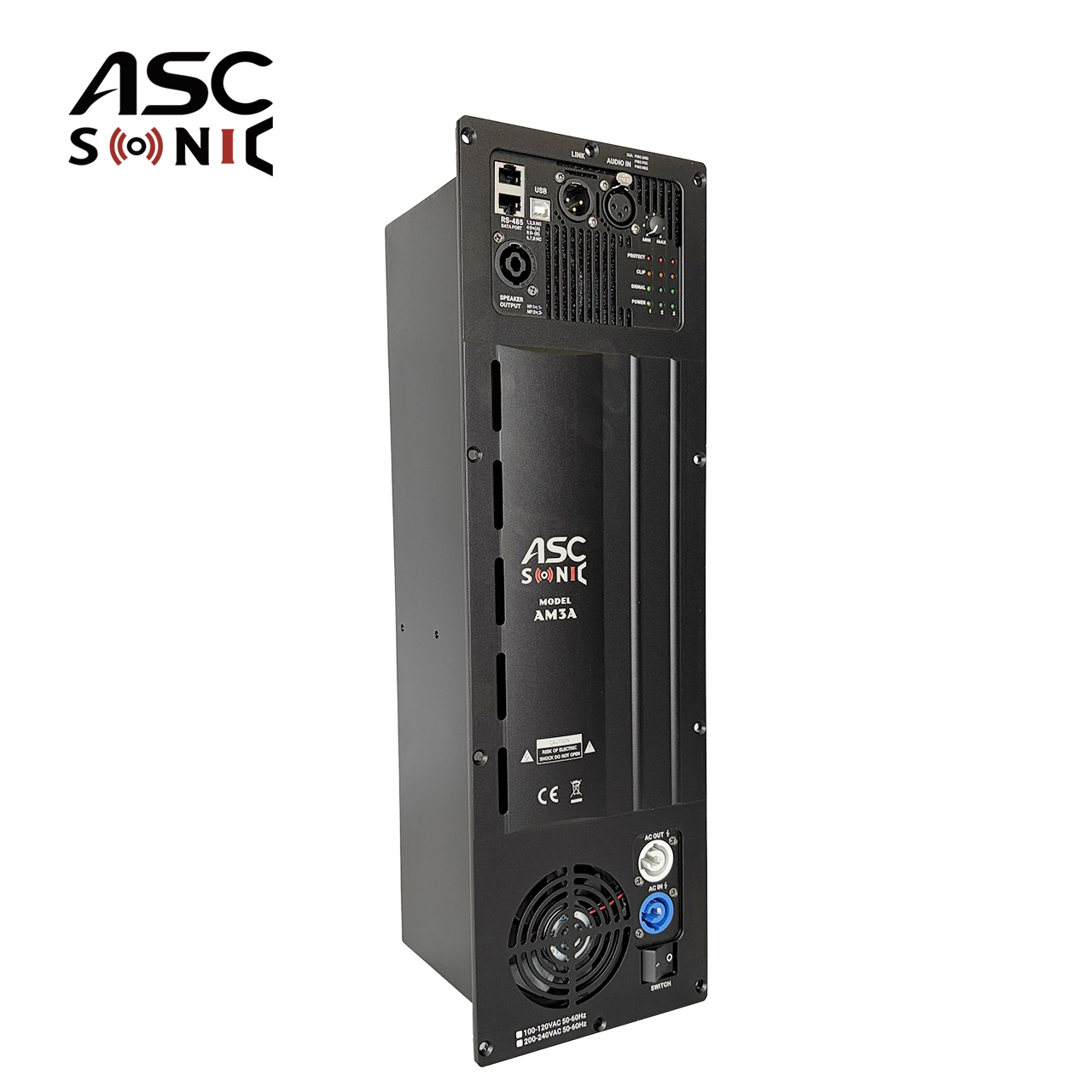
Powering passive stereo speakers alongside a dedicated subwoofer from a single back-panel unit presents a unique engineering challenge. Traditional mono or stereo amplifiers require external active crossovers, separate power supplies, and complex external wiring to achieve this. A dedicated 3 Channel Plate Amplifier solves this dilemma by providing independent power stages for the left, right, and subwoofer channels within a single, unified chassis. This all-in-one approach drastically reduces wiring complexity, eliminates ground loop issues between separate components, and streamlines the physical installation process into the speaker cabinet. You only need one power cable and one signal input source to drive an entire full-range audio system.
A multi-channel unit physically isolates the output stages of each channel. This architecture allows builders to safely run 8-ohm Left and Right satellite speakers while simultaneously driving a high-current 4-ohm subwoofer on the third channel. Because the channels operate independently from the main power rail, the heavy current draw of the 4-ohm subwoofer does not destabilize the voltage supplied to the 8-ohm stereo channels. This provides immense flexibility for custom speaker builders. You can select the best possible drivers for each frequency range without worrying about matching impedances across the entire system. The amplifier's internal power supply manages the current distribution automatically based on the demands of each isolated channel.
Onboard active crossovers are critical for the survival and performance of 2.1 systems. They ensure low frequencies are routed strictly to the subwoofer channel. This prevents over-excursion and mechanical distortion in the smaller satellite drivers, which are not designed to reproduce deep bass. When evaluating these amplifiers, verify that the crossover points and slopes are adjustable via the DSP interface. Proper frequency distribution maximizes the dynamic range of the entire speaker system. It ensures each driver only reproduces the frequencies it was mechanically optimized to handle. Setting a high-pass filter for the satellite speakers at 80Hz or 100Hz drastically reduces their thermal load and improves overall midrange clarity.
Impedance mismatching often reveals itself through severe thermal overload. If an amplifier frequently enters "protect mode" during dynamic audio peaks or heavy bass drops, it is likely seeing an impedance load lower than its design limits. The internal protection circuitry shuts down the output stage to prevent the silicon transistors from melting. While this protection saves the amplifier in the short term, continuous triggering of this mode degrades the amplifier's lifespan. The constant thermal cycling stresses solder joints and degrades the electrolytic capacitors on the circuit board. If your amplifier goes into thermal protect mode, you must immediately turn down the volume and verify your wiring configuration.
Demanding more current than an amplifier can supply into a 4-ohm load leads to a clipped waveform. Clipping flattens the rounded peaks of the audio signal, turning smooth sine waves into harsh square waves. This sends massive amounts of high-frequency distortion and continuous DC voltage directly to the speaker. A speaker voice coil relies on the alternating movement of the cone to pump cooling air over the wire. DC voltage stops this movement, causing rapid heat buildup that quickly burns out the voice coil, resulting in permanent driver failure. You can smell a burning voice coil long before the speaker stops working entirely. Proper impedance matching prevents the amplifier from reaching this destructive clipping threshold.
Some amplifiers feature physical impedance selection switches on the rear panel, often labeled "4-Ohm / 8-Ohm." Many experienced audio engineers recommend leaving the switch in the "8-Ohm/High" mode even when using 4-ohm speakers. The 4-ohm setting often severely limits the internal rail voltage to pass strict consumer safety and heat certifications. This effectively chokes the amplifier's dynamic power and headroom. Keeping the switch in the high setting preserves the amplifier's ability to deliver transient peaks. You can safely run the amplifier in this configuration provided you ensure rigorous thermal ventilation and do not push the amplifier into continuous clipping. Treat the switch as a voltage limiter rather than a strict impedance requirement.
Measure your speaker drivers' DC resistance with a digital multimeter to confirm their baseline nominal impedance before installation.
Calculate your total electrical load using series or parallel formulas if you are wiring multiple drivers to a single amplifier channel.
Cross-reference your calculated impedance figures with the plate amplifier's technical manual to verify absolute compatibility.
Set your DSP limiters to engage just below the amplifier's maximum unclipped output voltage to protect the voice coils.
A: Yes. Connecting a higher impedance speaker to a lower impedance-rated amp is perfectly safe. The amplifier will run cooler and more efficiently because the 8-ohm load restricts current flow. However, the amplifier will output less total wattage than its maximum 4-ohm rating.
A: The 4-ohm speaker will attempt to draw more current than the amplifier is designed to provide. This likely results in severe overheating, triggered protection circuits, distorted audio output, or permanent hardware failure of the amplifier's output transistors.
A: No. Impedance does not dictate audio quality or fidelity. A 4-ohm speaker simply draws more power at a given volume knob setting compared to an 8-ohm speaker of the exact same sensitivity, making it louder but not inherently better sounding.
A: It affects both. While safety is the primary concern, improper matching can degrade the amplifier's damping factor. This leads to loose, uncontrolled bass reproduction, and can negatively alter the speaker's intended frequency response across the audio spectrum.
A: Yes, provided each individual channel is rated for the load connected to it. It is common practice to run 8-ohm speakers on the stereo satellite channels and a heavier 4-ohm subwoofer on the dedicated low-frequency channel.
A: You can wire them in parallel to present a 4-ohm load, which maximizes power output if the amp is 4-ohm stable. Alternatively, wire them in series to present a 16-ohm load, which is incredibly safe but significantly reduces the total power output.


