
Views: 0 Author: Site Editor Publish Time: 2026-08-21 Origin: Site


The traditional approach to speaker design relies on passive crossover networks, which introduce inherent limitations regarding insertion loss, component tolerances, and phase anomalies. Achieving precise driver integration, flat frequency response, and accurate time alignment requires iterative, expensive modifications when using passive components. System designers and DIY audio engineers face diminishing returns when trying to correct acoustic anomalies post-amplification. Transitioning to an active plate amplifier with integrated Digital Signal Processing (DSP) shifts the tuning process from hardware modification to software control. This enables granular adjustments to crossovers, EQ, and phase before the signal reaches the amplification stage, while often streamlining the entire signal chain by directly supporting multiple audio sources.
Direct Driver Coupling: Active plate amplifiers eliminate passive crossover components between the amplifier and the driver, improving damping factor, power delivery, and transient response.
Granular Acoustic Control: Integrated DSP allows for precise time alignment, steep crossover slopes (up to 48dB/octave), and parametric EQ adjustments that are impossible to replicate with passive networks.
Subwoofer Optimization: Utilizing a DSP-equipped subwoofer plate amplifier enables exact room mode correction, seamless main-speaker integration, and high-pass subsonic filtering to protect drivers at high excursions.
System Simplification: Modern DSP plate amplifiers act as an all-in-one hub, replacing separate DACs, preamplifiers, and standalone DSP units by accepting digital and analog sources directly.
Implementation Requirement: Maximizing the value of a DSP amplifier requires external acoustic measurement tools (like REW and a calibrated microphone) to validate software adjustments.
Passive crossovers act as a physical barrier between the amplifier and the speaker driver. They rely on large inductors, capacitors, and resistors to divide audio frequencies. These components inherently degrade the audio signal. Large copper inductors introduce Direct Current Resistance (DCR). This resistance acts as a voltage divider, burning off amplifier power as heat and reducing the amplifier's damping factor, which leads to looser bass control and poor transient response. Capacitors suffer from Equivalent Series Resistance (ESR) and age over time, shifting the crossover point unpredictably.
Furthermore, passive components react to the impedance swings of the voice coil. As a driver heats up during heavy playback, its voice coil resistance increases. This thermal compression alters the crossover frequency dynamically, meaning the speaker sounds different at high volumes than it does at low volumes. Swapping high-quality passive components during the prototyping phase drains budgets rapidly. Prototyping a complex 3-way passive network often requires dozens of tightly toleranced parts, and a single mistake requires ordering an entirely new batch of components.
Active architecture fundamentally changes the signal path. It divides the frequency spectrum at the line level within the digital domain before any amplification occurs. An active DSP module assigns dedicated amplifier channels to specific drivers. One channel powers the tweeter, another powers the midrange, and a third powers the woofer. The amplifier connects directly to the driver's voice coil terminals.
This direct coupling maximizes power transfer and restores the amplifier's full damping factor. The DSP handles all filtering mathematically. Because the crossover happens digitally, voice coil temperature and impedance swings do not alter the crossover point. The digital filters remain perfectly stable regardless of playback volume or driver excursion. The amplifier maintains absolute control over the driver's motor structure, resulting in tighter, more accurate sound reproduction.
A successful active implementation achieves acoustic results impossible with passive parts. The primary indicator of success is a flat phase response through the crossover region. Drivers must sum perfectly without acoustic nulls or lobing errors. Another key criterion is maximized amplifier headroom. Since no power is lost to passive resistors or inductor heat, the system plays louder with less distortion.
Finally, a successful active system eliminates baffle step diffraction issues without relying on inefficient resistive padding. A speaker on a narrow baffle radiates bass in 360 degrees but midrange and treble in 180 degrees, causing a natural drop in low-frequency output. Passive designs use shelving filters that waste power to fix this. The DSP applies precise equalization to correct the baffle step at the line level, maintaining maximum system efficiency while delivering a flat on-axis frequency response.
DSP software provides absolute control over filter topologies. Users can select Linkwitz-Riley, Butterworth, or Bessel alignments instantly. Each topology offers distinct phase and summing characteristics. More importantly, DSP allows for incredibly steep crossover slopes, ranging from 12dB to 48dB per octave. Steep slopes are critical for advanced 3-way active configurations.
A 48dB/octave slope abruptly cuts off low frequencies, protecting fragile tweeters from damaging excursion. Steep slopes also minimize the overlap region between two drivers. Reducing this overlap narrows the frequency band where phase cancellation can occur, resulting in cleaner off-axis dispersion and a more focused soundstage. Passive networks rarely exceed 24dB/octave due to the sheer size, cost, and insertion loss of the required components.
Filter Topology Characteristics
| Filter Type | Phase Shift at Crossover | Amplitude Summation | Best Use Case |
|---|---|---|---|
| Linkwitz-Riley (LR4) | 360 degrees (In-phase) | Flat (0dB peak) | Standard 2-way and 3-way active monitors. |
| Butterworth (BW3) | 270 degrees | +3dB peak (requires offset) | Systems requiring maximum flat power response. |
| Bessel | Variable | Gradual roll-off | Applications requiring optimal transient response and linear phase. |
Physical driver placement rarely aligns acoustic centers perfectly. A tweeter's voice coil typically sits inches ahead of a woofer's voice coil on a flat baffle. This physical offset causes high frequencies to reach the listener's ear before low frequencies, smearing transient details. Passive networks attempt to fix this with physically stepped baffles or complex all-pass filter circuits that degrade the signal.
DSP solves this through digital time delay. By delaying the signal to the faster, closer driver, the software aligns the acoustic wavefronts perfectly at the listening position. Sound travels roughly one foot per millisecond. If a tweeter is two inches ahead of a woofer, the DSP applies a fraction of a millisecond delay to the tweeter channel. DSP handles these micro-second delays and phase inversion instantly. This digital alignment creates a coherent wavefront and completely eliminates the need for complex cabinet geometry.
Parametric Equalization (PEQ) offers surgical precision for frequency response correction. Unlike graphic equalizers with fixed bands, PEQ allows users to define the exact center frequency, the width of the adjustment (Q factor), and the amplitude gain or cut. This precision flattens inherent driver response anomalies, such as severe cone breakup modes in rigid metal drivers.
A magnesium or aluminum cone might have a massive 12dB resonance peak at 5kHz. A passive notch filter to suppress this requires massive, expensive components. A DSP handles it with a single, narrow PEQ cut. PEQ also manages room correction effortlessly. By measuring the room response, you can identify specific resonant frequencies that build up excessively and apply targeted cuts to restore clarity.
Premium active modules function as complete audio hubs. They accept multiple audio sources directly, including USB, Optical (TOSLINK), AES/EBU, and Bluetooth. Keeping the audio signal in the digital domain as long as possible prevents degradation. Traditional setups suffer from multiple digital-to-analog and analog-to-digital conversions across separate components.
A DSP plate amplifier internalizes this process. The digital signal routes straight into the DSP chip for processing, passing through a single, high-quality internal DAC immediately before the amplification stage. This streamlined path lowers the noise floor, preserves dynamic range, and eliminates the need for external preamplifiers or standalone DAC units.
Advanced DSP interfaces offer flexible input routing matrices. Users can direct any input channel to any output channel. A multi-channel plate amplifier easily configures into a dedicated 2-way or 3-way active studio monitor. Alternatively, builders can bridge specific channels to increase power output for demanding drivers.
You can configure a 3-channel plate amplifier to power a high-output 2.1 system from a single module. Two channels drive the left and right passive monitors, while the bridged third channel powers a dedicated subwoofer. This routing flexibility makes DSP amplifiers highly adaptable for various audio applications, allowing a single hardware platform to serve multiple distinct speaker designs.
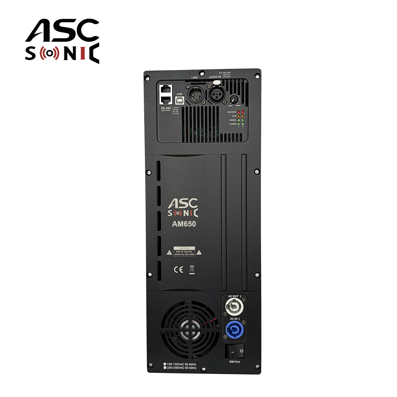
Matching the amplifier's output to the driver's limits ensures reliability. You must evaluate the RMS output of the Subwoofer Plate Amplifier against the thermal and mechanical limits of the subwoofer driver. Class D topology dominates this space due to its exceptional efficiency.
Class D amplifiers convert over 90% of drawn power into audio output, generating very little heat. This efficiency allows manufacturers to pack massive wattage into compact modules that fit easily on the back of a subwoofer enclosure. Adequate power reserves prevent amplifier clipping, which is the primary cause of voice coil failure in low-frequency drivers. A clipped signal sends sustained direct current to the voice coil, rapidly overheating the copper windings.
Subwoofers require specific protections to operate safely at high volumes. Ported enclosures unload the driver below the cabinet's tuning frequency (Fb). Without protection, the driver acts as if it is in free air, leading to catastrophic over-excursion where the voice coil former smashes into the backplate. DSP provides programmable high-pass filters, commonly known as subsonic filters. Setting a steep 24dB/octave high-pass filter just below the port tuning frequency protects the driver from mechanical damage.
For sealed enclosures, DSP utilizes Linkwitz Transform (LT) circuits. This specific mathematical algorithm extends the low-frequency response of a sealed box. An LT circuit can take a sealed box with a natural roll-off starting at 50Hz and electronically transform it to play flat down to 30Hz. This requires massive amplifier power at low frequencies, which modern Class D modules provide easily.
A subwoofer only sounds as good as its integration with the room and the main speakers. DSP evaluation must focus on phase matching capabilities. The software must allow precise phase adjustments to blend the subwoofer seamlessly with the main left and right speakers at the crossover point. If the subwoofer and main speakers are out of phase at the crossover frequency, they will cancel each other out, creating a massive dip in the mid-bass response.
Furthermore, low frequencies interact violently with room boundaries, creating resonant peaks and nulls known as room modes. DSP allows for targeted PEQ cuts to tame these specific resonant frequencies. By measuring the room response and cutting the exact frequencies that build up excessively, the DSP eliminates muddy, booming bass and restores low-frequency clarity.
Gain staging dictates the baseline performance of the entire system. It is the critical first step before any EQ or crossover adjustments begin. You must maximize the unclipped source signal from the upstream preamplifier or digital source. Set the source volume to a high, distortion-free baseline. Next, match the plate amplifier's input sensitivity to this incoming signal.
Proper gain staging maximizes the signal-to-noise ratio. If the input gain is too low, the amplifier must work harder to produce volume, which amplifies the inherent background noise. If the input gain is too high, the signal clips before it even reaches the DSP, causing harsh digital distortion. Once the input is optimized, adjust the individual output channel gains to match the varying sensitivities of your tweeters, midranges, and woofers.
Tuning an active system requires a strict, sequential methodology. Random adjustments lead to acoustic chaos. Industry professionals follow a specific order to ensure predictable results. You must establish the protective boundaries first, align the drivers in time, and only then apply equalization to smooth the final response.
Sequential DSP Tuning Workflow
| Tuning Phase | Action Required | Primary Goal |
|---|---|---|
| 1. Gain Staging | Match source output to amplifier input sensitivity. | Maximize signal-to-noise ratio; prevent digital clipping. |
| 2. Crossovers | Set high-pass and low-pass filters with appropriate slopes. | Protect drivers; define operational frequency bands. |
| 3. Time Alignment | Apply digital delay to faster/closer drivers. | Achieve phase coherence and transient accuracy. |
| 4. Level Matching | Adjust individual channel output volumes. | Balance driver sensitivities for a flat baseline response. |
| 5. Equalization (PEQ) | Apply targeted cuts and boosts using parametric EQ. | Smooth frequency response anomalies and correct room modes. |
DSP software is completely blind; it only executes the data fed into it. Tuning purely by ear is wildly inaccurate for complex active systems. Human hearing cannot reliably identify exact crossover phase nulls or specific millisecond delay requirements. Maximizing a DSP system demands acoustic measurement tools.
Software like Room EQ Wizard (REW) paired with a calibrated USB measurement microphone provides objective acoustic data. You must run frequency sweeps, analyze the impulse response, and view the phase traces to verify every DSP adjustment. You use a loopback timing reference to measure the exact acoustic delay between drivers. Measurement validates the software changes against the actual acoustic reality of the room, ensuring your mathematical inputs translate into accurate sound reproduction.
Active DSP amplifiers can introduce an audible noise floor, commonly perceived as a low-level hiss. This issue becomes particularly noticeable when pairing the amplifier with high-sensitivity drivers, such as compression tweeters or horn-loaded midranges that exceed 100dB/1W/1m sensitivity. The hiss originates from the internal DAC/ADC conversion stages and the amplifier's idle noise.
To mitigate this risk, carefully evaluate the Signal-to-Noise Ratio (SNR) specifications of the plate amplifier before purchase. Look for SNR values exceeding 100dB. Additionally, executing proper gain staging minimizes idle noise. If hiss persists on a highly sensitive tweeter, you can install a simple analog L-pad (a two-resistor voltage divider) between the amplifier output and the tweeter. This drops the noise floor below the threshold of hearing while allowing the DSP to handle all crossover and EQ duties.
Mounting a plate amplifier directly into a speaker cabinet exposes sensitive electronics to hostile internal conditions. High-output woofers generate massive internal air pressure and severe mechanical vibration. This pressure can cause air leaks through the amplifier's input jacks or control knobs, resulting in audible chuffing noises. Vibration can also fracture solder joints on the amplifier's PCB over time.
To mitigate these risks, you must design a sealed, isolated internal chamber specifically for the amplifier. Build a separate MDF enclosure inside the main cabinet. Route the speaker wires through sealed holes using acoustic caulk or silicone. This isolates the amplifier from internal pressure and mechanical stress while ensuring the external heatsink receives adequate ambient ventilation to dissipate heat.
Hardware longevity often outpaces software support in the digital audio realm. A significant risk involves the manufacturer abandoning software updates. If the DSP interface becomes incompatible with modern operating systems, the amplifier's tuning capabilities become inaccessible, rendering the DSP useless for future adjustments.
Mitigate this risk by evaluating the manufacturer's track record. Research their software update history and interface usability. Download the demonstration version of the software before buying the hardware. Check if the software runs natively on your current OS without requiring complex workarounds. Strong community support and active user forums often indicate a healthier, longer-lasting software ecosystem.
Purchasing an active DSP amplifier requires a higher initial investment compared to buying a bare passive crossover board. However, this upfront cost quickly offsets the iterative expenses of passive design. Prototyping a passive crossover demands purchasing multiple values of inductors, capacitors, and resistors to test different crossover points. High-end passive components, especially copper foil inductors and film capacitors, require significant material investment.
If a crossover point needs shifting by 500Hz in a passive system, you must buy entirely new passive parts. With a DSP amplifier, changing a crossover point costs nothing. You simply type a new number into the software and measure the result instantly. The iterative savings during the tuning phase make active designs highly cost-effective for custom builders who demand perfection.
Active DSP platforms offer unmatched long-term scalability. A passive crossover is hardwired for one specific combination of drivers and cabinet dimensions. If you upgrade your tweeters or change your woofer alignment, the passive crossover becomes obsolete. A DSP plate amplifier adapts to any future project.
You can repurpose the exact same amplifier for entirely different speaker builds simply by loading a new DSP preset. This flexibility ensures the hardware remains relevant as your audio requirements evolve. You can shift the amplifier from a 2-way bookshelf project to a 3-way tower project by simply reconfiguring the routing matrix and crossover parameters in the software.
Finalize your driver selection and cabinet volume parameters before selecting an amplifier module to ensure proper power matching and thermal limits.
Acquire a calibrated USB measurement microphone and install acoustic analysis software to capture objective room data for DSP validation.
Download and test demonstration versions of various plate amplifier DSP software to verify user interface compatibility with your operating system.
Construct a sealed, isolated internal chamber within your speaker cabinet to protect the amplifier module from internal air pressure and mechanical vibration.
A: A standard amplifier is a standalone unit requiring external preamplifiers and crossovers. A plate amplifier mounts directly into a speaker cabinet. An active plate amplifier includes built-in DSP and multiple channels to power individual drivers directly, completely bypassing the need for passive crossover networks inside the speaker.
A: No, passive crossovers are entirely removed for the frequencies handled by the DSP. The amplifier connects directly to the driver. However, builders often retain a single, high-quality protection capacitor in series with fragile tweeters to block accidental DC pops or turn-on thumps.
A: The DSP uses narrow-band Parametric EQ (PEQ) cuts to reduce specific frequencies that resonate and build up excessively in a given room. By measuring the room's acoustic response, you can identify these peaks and apply precise digital cuts, resulting in tighter, more accurate bass response.
A: While broad EQ changes and general volume levels can be adjusted by ear, precise tuning requires measurement. Setting exact time alignment delays, verifying phase coherence at the crossover point, and identifying narrow room modes demand a calibrated microphone and acoustic analysis software.
A: You need two types of software. First, you need the proprietary control software provided by the amplifier manufacturer to adjust the DSP settings. Second, you need acoustic measurement software, such as Room EQ Wizard (REW), to measure the actual sound output and guide your DSP adjustments.
A: Yes. While designed for internal mounting, plate amplifiers can operate externally. Builders often construct standalone, well-ventilated wooden or metal enclosures for the plate amp. This keeps the electronics completely isolated from cabinet vibrations and makes rear-panel wiring adjustments easier during the tuning process.


