
Views: 0 Author: Site Editor Publish Time: 2026-08-20 Origin: Site


Custom speaker building and professional audio have moved away from heavy external amplifier racks and complex passive crossovers. We now rely on self-contained, powered loudspeaker designs. Passive speaker design forces you to fight power loss through crossover components. You struggle with driver time-alignment and face the headache of matching external amplifiers to specific driver impedances. An active plate amplifier fixes these structural and electronic problems for modern powered speakers. This guide breaks down how these modules operate on the bench. We will look at digital signal processing integration and the technical criteria you need to evaluate and select the right unit for your specific speaker build.
An active plate amplifier integrates the power supply, amplification circuitry, and input stage onto a single metal chassis that serves as both a structural cabinet component and a thermal heatsink.
By bypassing passive crossovers, active plate amplifiers connect directly to speaker drivers, drastically improving damping factor, efficiency, and transient response.
A DSP plate amplifier provides precise digital control over crossover slopes, parametric EQ, time alignment, and driver protection (limiting), eliminating the need for outboard processing.
Selecting the correct module requires evaluating RMS power ratings per channel, impedance matching, thermal management constraints within the enclosure, and input connectivity requirements.
The internal architecture of these modules relies on three primary electronic stages to convert AC wall power into a high-fidelity audio signal. The first stage is the power supply. Modern units utilize a switch-mode power supply (SMPS) rather than heavy toroidal transformers. In the past, massive copper transformers would literally rip out of MDF cabinets during transport due to their sheer weight. An SMPS rapidly switches transistors on and off to regulate voltage, drastically reducing the physical weight and footprint of the module while maintaining high current delivery. The second stage is the preamplifier and input section, which receives the incoming audio signal, buffers it, and applies initial gain. The final stage is the power amplification module itself. Most contemporary designs employ Class-D amplification topologies due to their exceptional electrical efficiency and minimal heat generation.
Power supply voltage handling requires specific mechanical configurations to accommodate global electrical standards. Many modules feature a 110V/240V selector switch. This mechanical switch alters the configuration of the primary input capacitors. When set to 110V, the capacitors operate in parallel to handle the lower voltage and higher current. When switched to 240V, the circuit places these capacitors in series, safely managing the higher incoming voltage without catastrophic component failure. Auto-switching power supplies handle this routing dynamically via internal relays and sensing circuits.
Engineers mount the amplification circuitry directly to a thick aluminum or steel plate rather than housing it in a separate external chassis. The metal plate is usually 3mm to 5mm thick. This design choice serves two distinct functions. First, the plate acts as a rigid structural panel. When screwed into the rear cutout of a speaker cabinet, it completes the acoustic enclosure, sealing the internal air volume necessary for proper driver loading. The metal must resist flexing under the intense internal air pressures generated by woofer excursion.
Second, the metal plate functions as a massive thermal heatsink. Amplification circuits generate thermal energy that you must dissipate to prevent thermal shutdown or component degradation. By mounting the output transistors directly to the inside surface of the metal plate, heat transfers conductively to the exterior panel. The ambient air outside the speaker cabinet then cools the plate via natural convection. To ensure the plate performs its structural role without introducing air leaks, builders follow a strict installation sequence:
Route a recessed flange into the rear wooden baffle using a rabbeting bit to ensure the metal plate sits perfectly flush with the cabinet exterior.
Apply a continuous strip of closed-cell EVA foam gasket tape around the inner lip of the routed recess.
Pre-drill pilot holes for every mounting screw to prevent the MDF or plywood from splitting under torque.
Drive the mounting screws in a star pattern, similar to changing a car tire, to apply even pressure across the entire gasket.
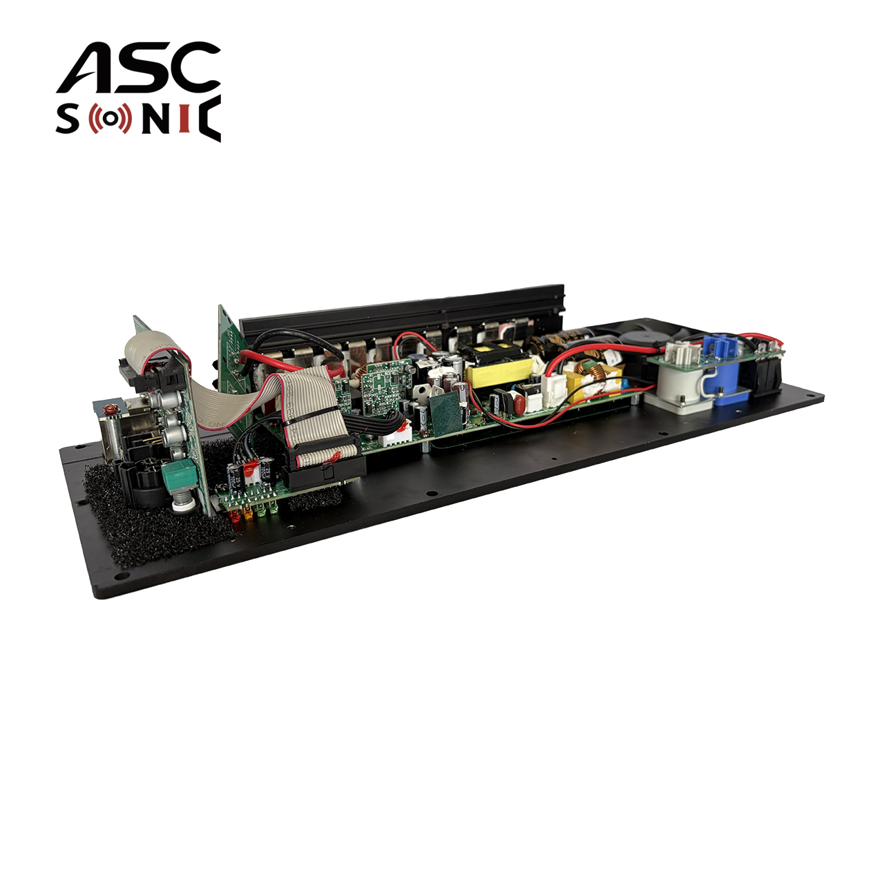
The audio signal path begins at the physical input panel, which offers balanced XLR, unbalanced RCA, or digital connections. Balanced inputs utilize a differential signaling method to reject common-mode noise picked up along long cable runs. Once the signal enters the pre-amp stage, it is buffered and routed into the active crossover network. Unlike passive systems that divide frequencies after amplification, active systems divide the line-level signal first. The low frequencies route to a dedicated low-frequency amplifier channel, while the high frequencies route to a separate high-frequency channel. Each amplifier module then boosts its specific frequency band to speaker-level voltages.
Traditional passive speakers rely on external binding posts, requiring thick speaker cables to travel from an external amplifier to the cabinet. Plate amplifiers eliminate this external run. They utilize internal wiring harnesses equipped with spade connectors or locking Molex terminals. These internal cables connect the output stage of the amplifier directly to the speaker driver's voice coil terminals. We typically use 14 AWG wire for subwoofer channels and 18 AWG wire for high-frequency tweeters.
Routing these internal cables requires strict acoustic isolation. When wires pass from an isolated amplifier chamber into the main acoustic volume of the speaker cabinet, the pass-through holes must be completely airtight. Builders use dedicated cable glands or heavy applications of polyurethane construction adhesive to seal the hole. Even a microscopic gap around a wire pass-through causes audible chuffing or whistling noises during heavy bass passages.
Direct amplifier-to-voice-coil connections provide massive electrical and acoustic advantages. Passive crossovers sit between the amplifier and the driver, utilizing large inductors, capacitors, and resistors to filter frequencies. These passive components introduce electrical resistance, which burns off amplifier power as heat and alters the phase response of the audio signal.
Eliminating these passive components dramatically improves the amplifier's damping factor. Damping factor represents the amplifier's ability to control the physical motion of the speaker cone. A woofer cone has physical mass. When a bass note stops, momentum makes the cone want to keep moving. The amplifier acts as an electronic brake to stop it. Passive inductors placed in series with a woofer severely degrade this braking ability. A direct connection allows the amplifier to exert maximum electrical grip on the voice coil, resulting in tighter, more articulate bass response.
System Architecture Comparison
| Feature | Passive Crossover System | Active Direct Drive System |
|---|---|---|
| Signal Division | Post-amplification (Speaker Level) | Pre-amplification (Line Level) |
| Power Efficiency | Low (Power lost as heat in components) | High (Direct connection to voice coil) |
| Damping Factor | Degraded by series inductors | Maximum control over driver motion |
| Phase Coherence | Difficult to align perfectly | Digitally aligned via DSP delay |
A DSP Plate Amplifier handles frequency division entirely within the digital domain before the signal reaches the amplification stage. The incoming analog signal passes through an Analog-to-Digital Converter (ADC), allowing the internal microprocessor to apply complex mathematical algorithms to the audio data. This digital approach allows builders to implement steep, phase-coherent crossover slopes that are physically impractical or prohibitively expensive to achieve with passive components.
You can select a 24dB/octave Linkwitz-Riley crossover profile with a few mouse clicks. This steep slope ensures that the tweeter and woofer do not overlap excessively at the crossover frequency, reducing phase cancellation and off-axis lobing. Attempting to build a passive 24dB/octave crossover requires dozens of expensive, tightly matched copper foil inductors and film capacitors, which still cannot match the precision of digital filtering.
Digital signal processing grants builders absolute control over the frequency response of individual drivers. Raw speaker drivers rarely exhibit perfectly flat frequency responses. They suffer from cone breakup modes, baffle step diffraction, and resonance peaks. A DSP interface provides multiple bands of fully parametric equalization (PEQ) per channel. You pinpoint specific frequency anomalies, adjust the Q-factor (bandwidth) of the filter, and apply precise cuts or boosts to flatten the driver's response perfectly.
Time alignment is another function impossible to achieve perfectly in the analog domain without physically staggering the drivers. In a typical flat-baffle speaker, the acoustic center of the tweeter sits further forward than the acoustic center of the deeper woofer cone. This physical offset causes high frequencies to reach the listener's ear milliseconds before the low frequencies, smearing transient details. DSP solves this by applying digital delay to the tweeter channel, perfectly aligning the arrival times of all frequencies at the listening position.
Active modules safeguard the entire speaker system through advanced digital limiting. DSP interfaces offer two distinct types of protection. RMS limiters monitor the continuous average power delivered to the voice coil. If the power exceeds the thermal limits of the driver for a sustained period, the RMS limiter gently compresses the signal, preventing the voice coil insulation from melting. Peak limiters act instantaneously to catch sudden, massive voltage spikes. By clamping down on these spikes, peak limiters prevent the speaker cone from exceeding its maximum mechanical excursion (Xmax), thereby preventing physical destruction of the suspension.
The baseline application for this technology is the powered sub plate amplifier. These are dedicated 1-way solutions designed exclusively to drive low-frequency transducers. They feature a single, high-output amplifier channel and built-in low-pass filters to strip away midrange and treble frequencies. Because they are application-specific, they include specialized features like variable phase dials (0-180 degrees) and parametric bass boost circuits to compensate for low-frequency room modes. We often set a high-pass filter at 20Hz on these modules to prevent the subwoofer from destroying itself trying to reproduce subsonic frequencies.
Moving beyond subwoofers introduces the complexity of multi-way active speaker builds. Two-way and three-way multi-channel plate amplifiers allocate dedicated amplifier modules to specific frequency bands within a single full-range enclosure. A 2-way module provides one channel for the woofer and one for the tweeter. A 3-way module adds a dedicated channel for a midrange driver. True 4-channel plate amps for 4-way active systems are exceptionally rare due to the massive physical footprint required for four separate output stages and the complex DSP routing required. Builders constructing 4-way systems compromise by using a 3-way active module and employing a single passive crossover between the midrange and tweeter.
Multi-channel modules rarely offer identical power outputs across all channels. They feature asymmetrical power distribution based on the natural energy distribution of audio signals. Low frequencies require massive voltage swings and high current to move large, heavy woofer cones against the air pressure inside the cabinet. High-frequency tweeters feature ultra-light moving masses and require very little power to achieve high sound pressure levels.
A typical 3-way module provides 500 watts for the low-frequency driver, 150 watts for the midrange, and 50 watts for the high-frequency driver. This asymmetrical layout optimizes the power supply's efficiency. If the module provided 500 watts to the tweeter, that power capacity would be entirely wasted. Applying even 100 watts to a standard dome tweeter instantly vaporizes its voice coil.
Matching amplifier output to driver requirements demands careful attention to technical specifications. The critical metric is the continuous Root Mean Square (RMS) power rating measured at a specific impedance level. Inflated "Peak," "Max," or "Dynamic" wattage claims represent transient bursts lasting only fractions of a second and hold no value for continuous system design.
Impedance matching dictates how much power the amplifier can safely deliver. An amplifier rated for 500W RMS at 4 ohms delivers roughly half that power (250W RMS) into an 8-ohm load due to the increased electrical resistance. Connecting a 2-ohm driver to an amplifier only rated for a minimum 4-ohm load causes the amplifier to draw excessive current, triggering thermal shutdown or catastrophic failure. You must verify the nominal impedance of your specific drivers and cross-reference it with the amplifier's rated output at that exact impedance.
Amplifier Topology Comparison
| Topology Type | Efficiency | Heat Generation | Physical Footprint | Primary Application |
|---|---|---|---|---|
| Class D | 80% - 90% | Very Low | Compact / Lightweight | Subwoofers, High-Power Woofers, Modern Full-Range |
| Class AB | 50% - 60% | High | Large / Heavy Heatsinks | High-Frequency Tweeter Channels, Audiophile Monitors |
The choice of amplification topology directly impacts the physical design of the speaker enclosure. Class D modules dominate the modern market. Their switching transistor design achieves 80% to 90% electrical efficiency, meaning almost all incoming wall power converts directly to audio output. This high efficiency results in minimal heat generation, allowing for highly compact circuit boards and smaller external metal plates. They are the standard for subwoofer and high-power woofer applications.
Class AB modules operate differently, keeping their output transistors partially biased at all times to eliminate crossover distortion. While favored by some builders for high-frequency channels due to perceived sonic warmth, Class AB designs are highly inefficient. They waste up to 40% of their power as heat. Integrating a high-power Class AB module requires massive, heavy external heatsink fins protruding from the back of the speaker to prevent overheating.
The hardware is only as capable as the software controlling it. Evaluating the manufacturer's DSP control software before purchase is a mandatory step in the selection process. The graphical user interface (GUI) must provide intuitive access to routing matrices, filter types, parametric EQ bands, delay settings, and limiter thresholds. Poorly coded software with a confusing interface severely bottlenecks the tuning process.
Connectivity options for real-time tuning vary by manufacturer. Basic modules utilize a direct USB connection to a laptop. Advanced professional modules feature Ethernet ports, allowing builders to network multiple speakers together and tune an entire system simultaneously from a central computer. Some modern iterations incorporate Wi-Fi modules for wireless tuning via tablet applications, offering maximum mobility when measuring acoustic responses in different parts of a room.
The intended application dictates the required input connectivity. Home theater and consumer audio builds rely on unbalanced RCA inputs or standard speaker-level inputs. Professional studio monitors and live sound reinforcement systems require balanced XLR inputs to reject electromagnetic interference over long cable runs. High-end installations demand digital inputs, such as AES/EBU or SPDIF, to keep the signal in the digital domain from the mixing console directly to the amplifier's DSP. Networked audio protocols, primarily Dante, allow audio routing over standard Cat5e/Cat6 Ethernet infrastructure.
Mounting a metal plate into a wooden cabinet introduces severe acoustic risks. The cutout required to house the module compromises the structural integrity of the enclosure. If the mating surface between the metal plate and the wooden cabinet is not perfectly flush, high-pressure air leaks out during woofer excursion. This air leak acts as an unintended port, altering the cabinet tuning and producing highly audible whistling noises. You mitigate this by routing a recessed lip into the cabinet wood and applying continuous strips of closed-cell EVA foam gasket tape beneath the perimeter of the plate before tightening the mounting screws.
Mechanical stress presents another significant risk. Mounting sensitive electronic circuit boards directly inside a subwoofer enclosure subjects the components to violent, continuous vibration. Over time, these vibrations fracture solder joints, snap capacitor leads, and loosen internal wiring harnesses. High-quality modules combat this by applying heavy vibration-resistant potting compounds over large capacitors, inductors, and sensitive board connections to lock them physically in place.
The internal volume and acoustic alignment of the speaker cabinet directly affect amplifier cooling. In a ported cabinet, air constantly moves in and out of the enclosure, providing a degree of internal air circulation over the circuit boards. In a sealed acoustic suspension cabinet, the internal air volume is trapped. The heat generated by the internal components has nowhere to go, raising the ambient temperature inside the box and potentially leading to premature capacitor failure.
To solve both vibration and thermal issues, professional builders construct a separate, sealed internal chamber specifically for the plate amplifier. This isolated sub-enclosure protects the electronics from the violent pressure fluctuations of the main acoustic chamber. Building this chamber requires specific steps:
Calculate the volume of the amplifier chamber and subtract it from the total internal volume of the speaker cabinet to ensure your woofer still has enough airspace.
Construct the chamber walls using 3/4-inch MDF or Baltic Birch plywood.
Seal all internal joints of the chamber with heavy construction adhesive.
Drill a small hole for the speaker wires to pass through, and seal the hole completely with silicone or polyurethane caulk once the wires are routed.
Active plate amplifiers represent the most efficient path to building high-performance, bi-amplified or tri-amplified powered speakers, provided the enclosure is designed to accommodate their structural and thermal requirements. By eliminating passive crossover networks and integrating precise digital signal processing, these modules grant builders unprecedented control over driver integration, time alignment, and system protection.
To move forward with your build, follow these exact steps:
Calculate your required internal cabinet volume and verify that the physical cutout dimensions of your chosen amplifier will fit on the rear baffle without cutting into structural bracing.
Download the manufacturer's DSP software to evaluate the user interface and ensure it provides the specific crossover slopes and EQ bands you need.
Map out your internal wiring routes and purchase the necessary cable glands or sealants to guarantee complete acoustic isolation between the amplifier chamber and the main speaker volume.
Verify the nominal impedance of your speaker drivers and confirm the amplifier delivers adequate RMS power at that specific impedance load.
A: A regular amplifier is housed in a standalone external metal chassis and connects to passive speakers via external speaker wire. A plate amplifier is an exposed circuit board mounted to a flat metal panel. It is designed to be physically screwed into the back of a speaker cabinet, utilizing internal wiring harnesses to connect directly to the speaker drivers.
A: Generally, no. Subwoofer modules feature built-in, often non-bypassable low-pass filters designed specifically to block midrange and high frequencies. Unless the module is explicitly designed as a full-range unit or allows you to completely disable the internal low-pass crossover via DSP, it will muffle or block the audio intended for tweeters and midrange drivers.
A: It is an active amplifier module that incorporates Digital Signal Processing directly onto the board. Instead of relying on analog components, it uses a microprocessor to handle active crossover slopes, parametric equalization, time-alignment delays, and peak/RMS limiting before the audio signal is amplified.
A: You must ensure a perfectly airtight fit to prevent whistling and air leaks. Apply a continuous strip of closed-cell EVA foam gasket tape around the inner perimeter of the amplifier's mounting flange. For optimal isolation, build a separate, sealed wooden chamber inside the main cabinet exclusively to house the amplifier module.
A: Most modern Class-D modules are highly efficient and rely entirely on the external metal mounting plate acting as a passive heatsink to dissipate heat into the ambient room air. However, if mounted in extremely tight, unvented internal chambers or pushed to maximum output continuously, external airflow or dedicated venting may be required to prevent thermal shutdown.
A: Look strictly at the continuous RMS power rating, ignoring peak or dynamic wattage. Determine the nominal impedance of your speaker driver and ensure the amplifier can deliver an RMS wattage at that specific impedance that closely matches or slightly exceeds the driver's RMS power handling capability.


